A Vacuum Diode for Make: Magazine
Scroll DownAfter my presentation at Hackaday Superconference 2022 I was asked by my friend David to write a piece for Make: Magazine. I originally wrote the article around the diode tube that I presented at Supercon. However, because I had built that tube hastily in the days before the conference, I didn’t have a lot of good photos of the process. I decided the best thing to do was to make another tube specifically for the Make: article and take care to document the process this time.
The article ran in Make: Volume 86 but couldn’t contain all of the photos that I took at full resolution, so I thought it would be fun to go over them in more detail here.
The Ol’ Flare and Pinch
The hardest part of making a vacuum tube is fabricating the base, where the pins pass-through from atmosphere to the high-vacuum side. The easiest way to achieve this as a hobbyist is the pinch method. With the proper combination of metal and glass, a pinch seal can be extremely robust. Because I prefer to work with borosilicate glass, my feed-through metal needs to be Tungsten (although Molybdenum foil also works as well as specialty alloys such as Kovar). To make a vacuum-tight pinch, the Tungsten wire needs to be cleaned to remove any oils and other junk and then treated with a flame to apply a layer of oxide. The Tungsten oxide is what actually binds the metal to the glass so it’s important to have a uniform film. This sounds more difficult than it is. I’ve made good working seals by cleaning the wire with alcohol and then heptanes, passing it over a flame until white hot, then rubbing off the loose oxide with a cotton swab. This method is demonstrated by jdflyback in this YouTube video about building a handmade triode.
Because Tungsten is brittle, I first spot-weld short Tungsten pins onto longer pieces of Nickle wire. The Nickle is more mechanically forgiving and readily welds to the Tungsten, while the Tungsten portion wets to the glass and creates our seal.
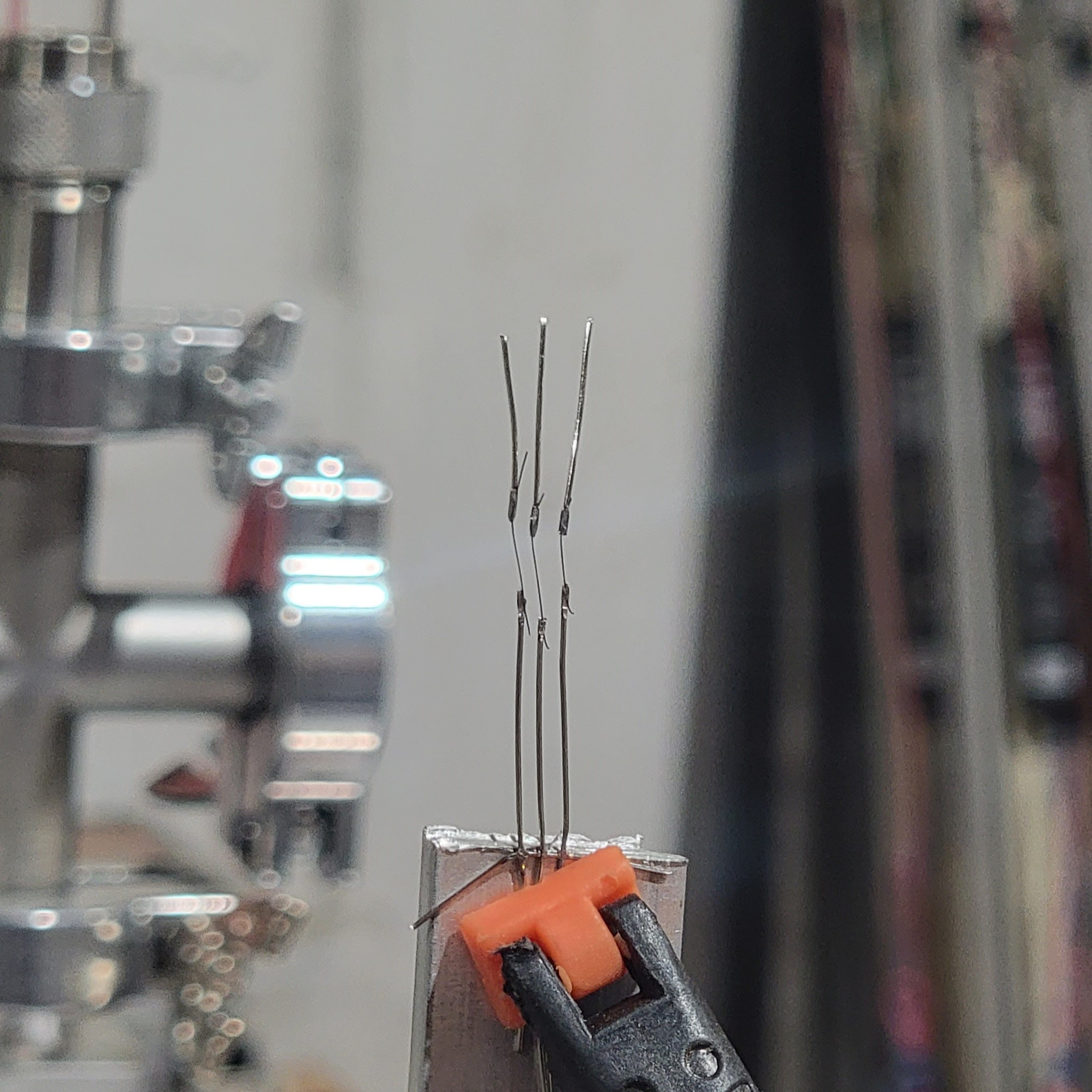
Once the pins are prepared, we need a piece of glass to pinch them in. The glass needs to be a smaller diameter than the tubing for the envelope of the tube so that once it’s pinched, it still fits inside. That’s why the end is flared, to make it easier to join with the envelope.
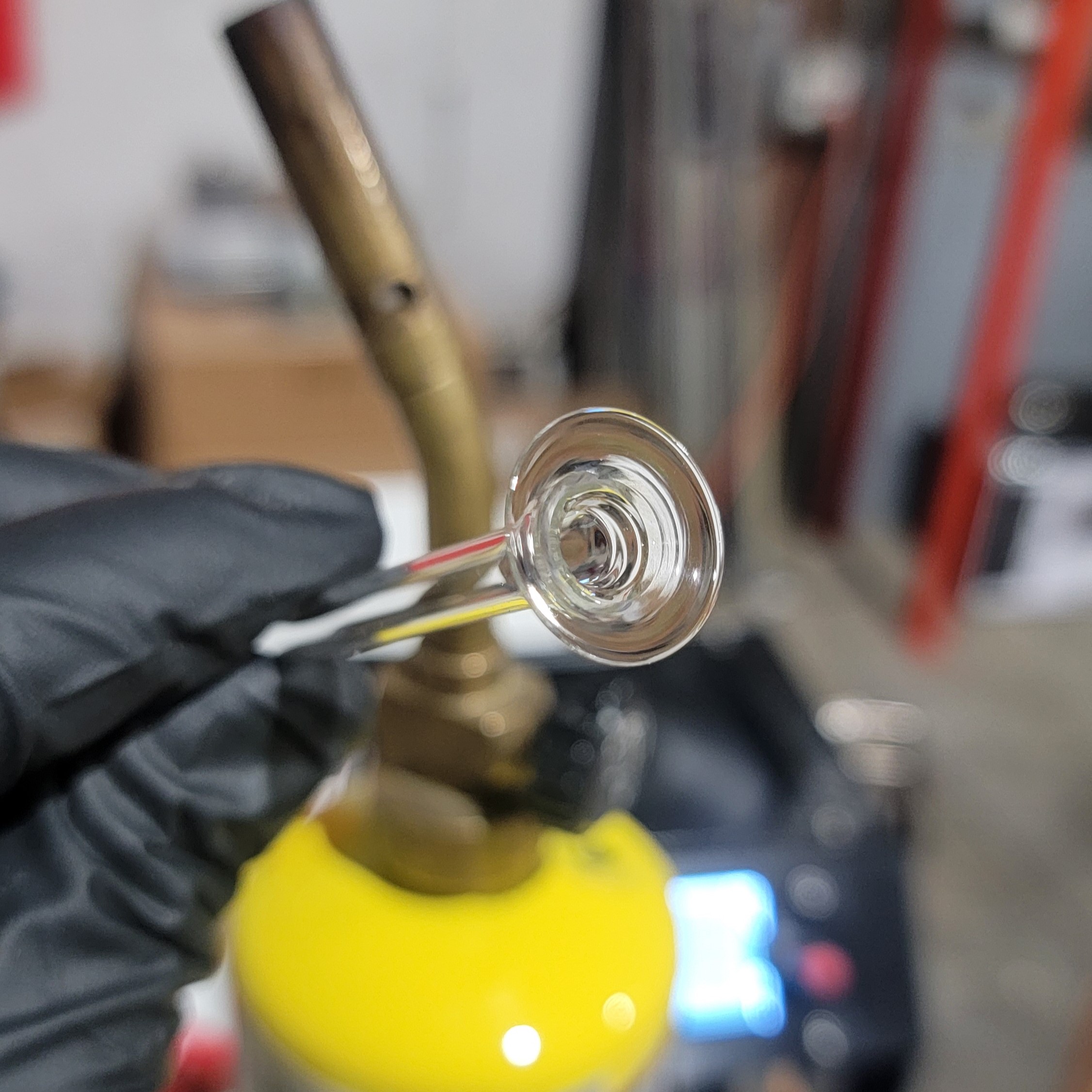
To make the flare, I simply chucked up the tubing in a power drill and heated the end with a MAPP gas torch while turning it. I nudged it gently with a tool to get the end to flare. Ideally, I would do this in the glass lathe, but I haven’t made a collet to hold these small parts. After the flare is made, I pre-flatten it just enough to support the wires before the pinch.
To actually make the pinch, the pins are inserted into the flare and then the flare is heated to softness with an oxy-propane flame. I usually make a preliminary pinch, to capture the pins in place before heating the glass more thoroughly to make the final pinch. I’ve tried various tools to do the pinch. First I used smooth jawed pliers, but it’s difficult to make an even pinch that way because they don’t close parallel. Then I tried large tweezers, because they’re slightly more parallel but it’s difficult to put enough pressure on the pinch. I have my sights set on a pair of smooth jaw, brass parallel pliers which I’ve yet to try, but I suspect will work quite well.
Assembling the Active Elements
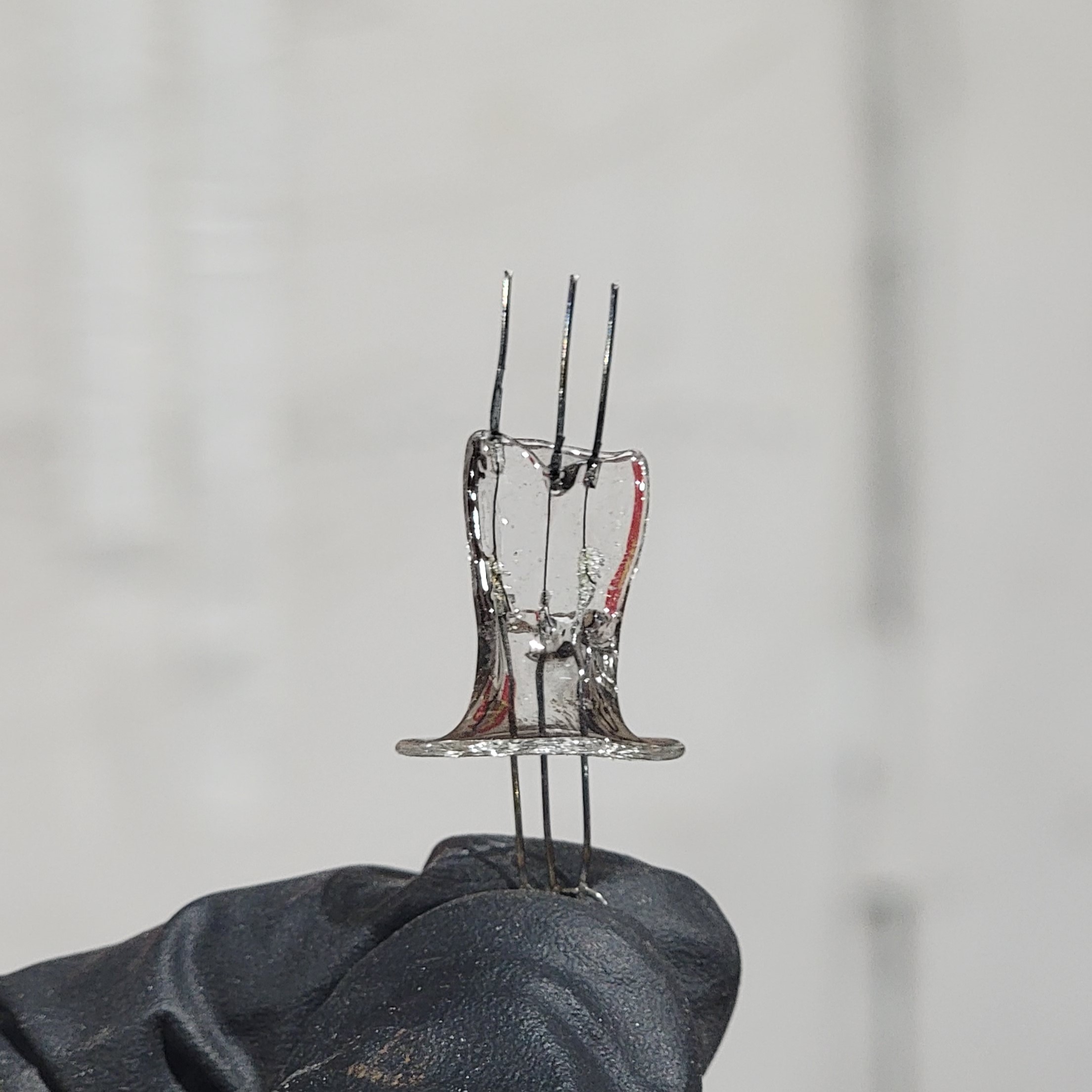
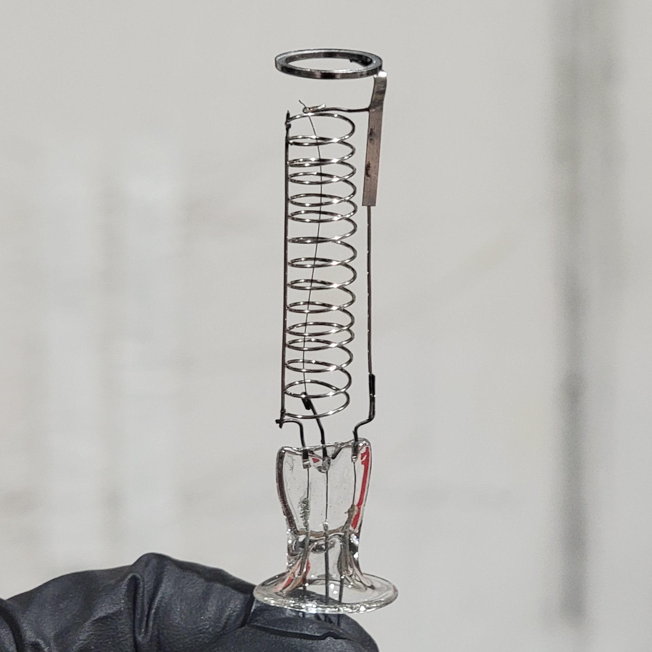
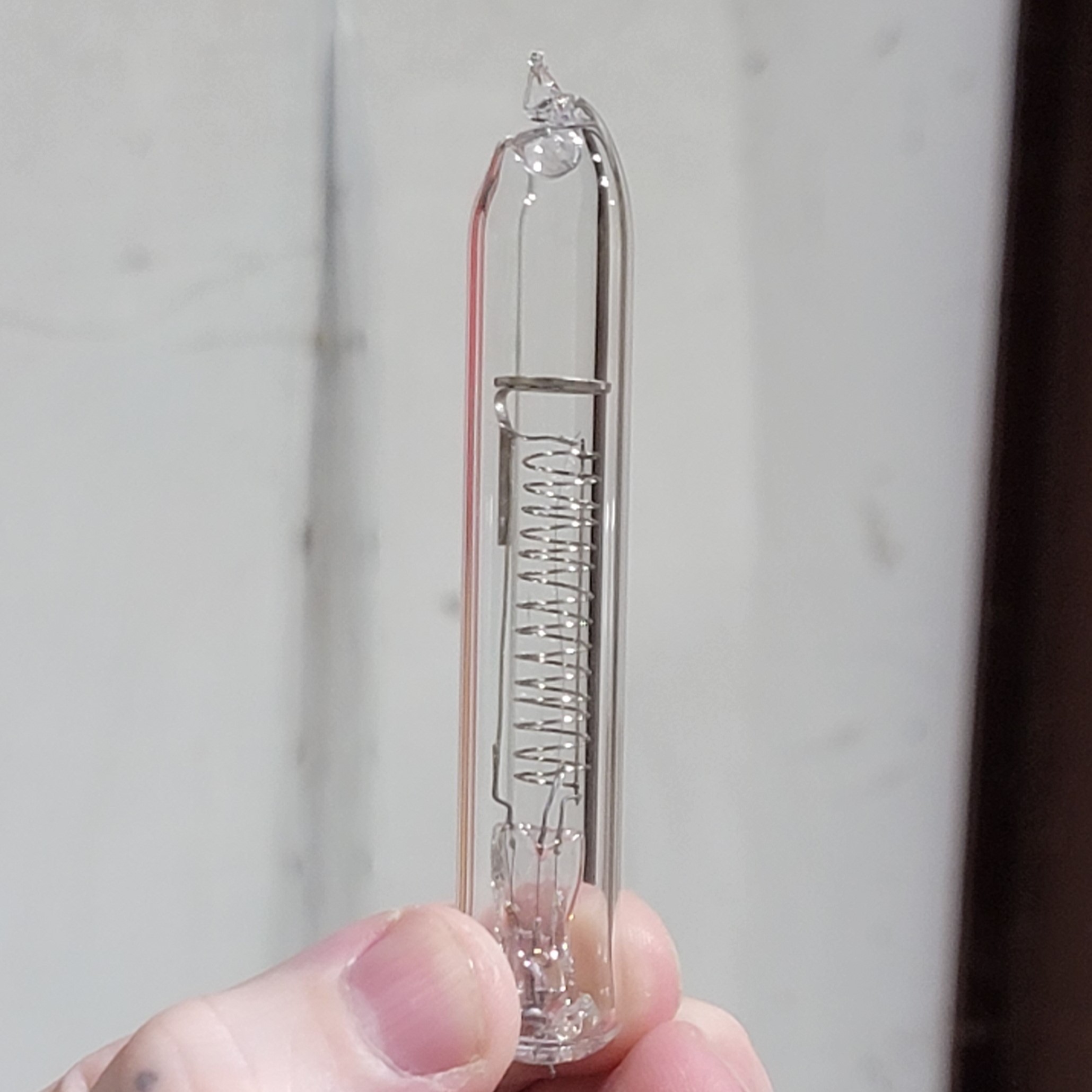
This is the base that we’ll build the rest of the diode on top of. For this directly heated diode, we’ll just need two elements: a tungsten filament, and a coil of wire to act as the plate. I formed the coil out of Nickel wire around the shaft of a screwdriver and then made filament supports out of Nickel wire as well. All of these parts were spot welded to the pins on the base before getting a thorough cleaning with alcohol and heptanes. After the washing, but before being welded into the envelope, the assembly gets an evaporable getter (the small ring at the top). The getter contains Barium metal which we’ll evaporate after the tube is evacuated in order to sequester any oxygen molecules that migrate off of the metal during operation. This helps to maintain the integrity of the vacuum.
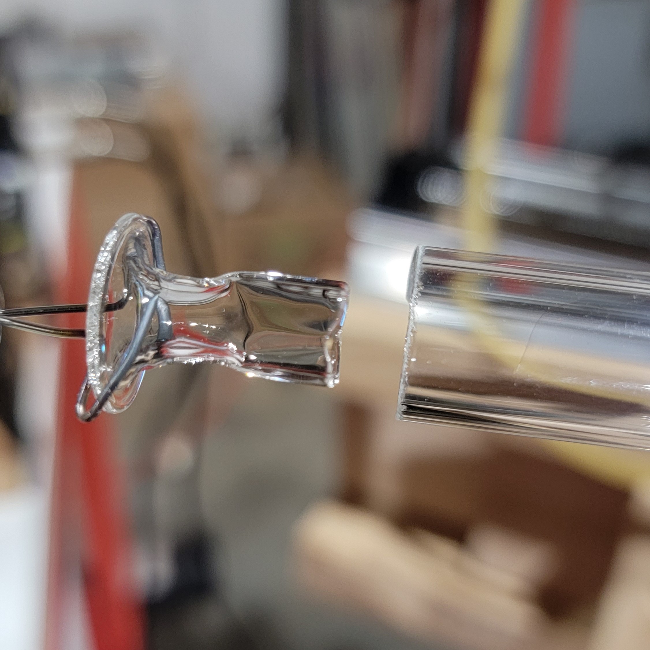
Now I just need to stuff all of this into a piece of glass tubing. Here’s an idea of how the flare fits into the envelope.
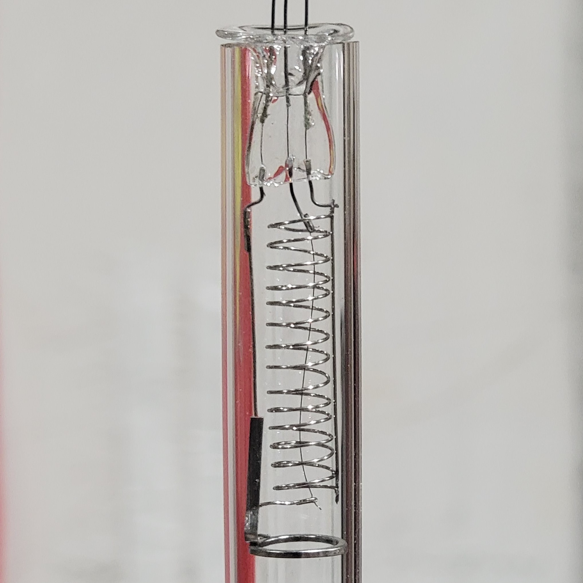
While the piece is upright like this, the flare was tacked in place with a small oxy-propane flame. Then the piece was moved to the lathe so finish up the glass seal around the base. Careful heating and gentle pressure to prevent it from collapsing resulted in a serviceable joint.
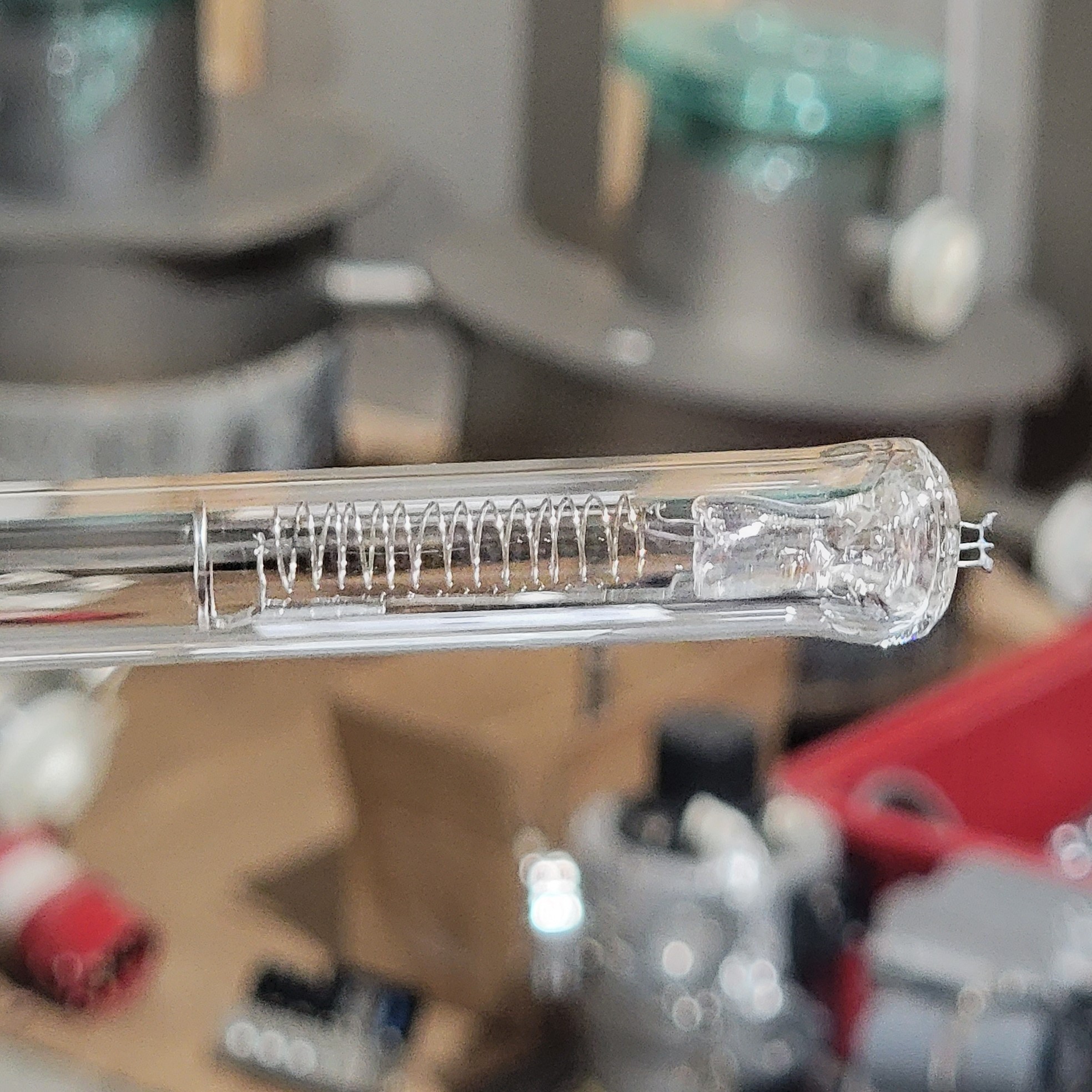
This tubing is sized to fit into a quick connect on the vacuum system, but to aid the separation, I heat the tubing above the assembly and pull it to make a neck.

Big Succ
And now we’ve reached arguably the easiest, but most nerve-wracking stage: Evacuation. The whole assembly goes into a compression fitting at the top of the evacuation bench. This system will be the subject of a whole other write-up, but it’s essentially a collection of vacuum pumps and gauges.

During pumpdown, the tube is heated with a propane torch to drive off any adsorbed water. The internals are heated with an induction coil. Finally, the filament is powered to a dim glow to drive out oxygen.
And now the step where I can ruin everything extremely quickly! Gently heating the neck of the tube with a propane torch until it begins to soften and close in on itself, I use my other hand to twist and pull the tube away from the vacuum system. If all goes well, both pieces of glass will remain sealed, and the tip-off will be complete.
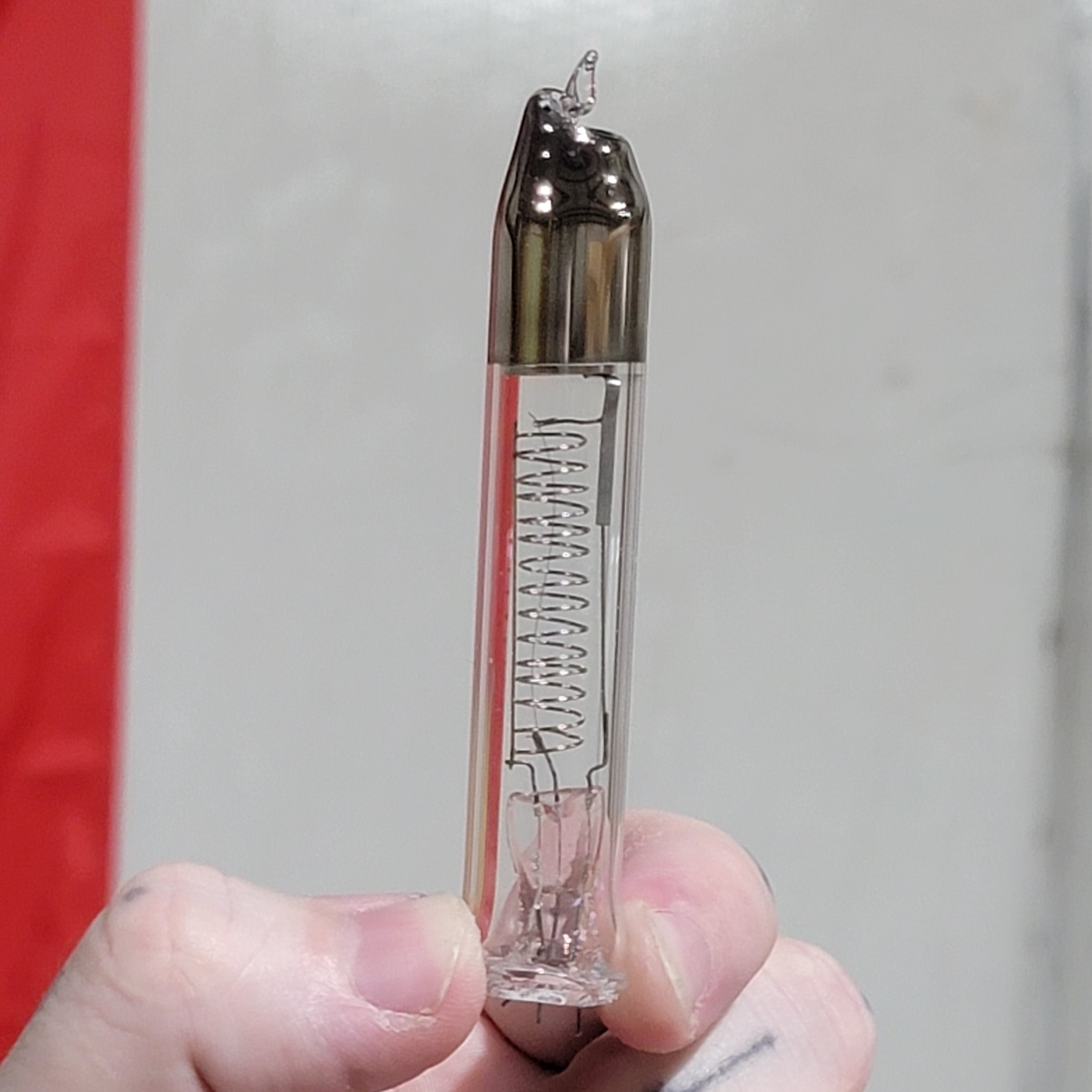
After the tube is tipped off, the only thing left to do is to fire the getter. To do this, I use an induction heater designed to loosening rusted bolts. I bought mine on eBay for under $200. All you have to do is put the coil around the tube and line it up so it’s concentric with the getter ring. After a few seconds, the ring will get red hot and you’ll see a mirror developing on the glass above it, this is the getter material. This mirror of reactive Barium metal will react with oxygen in the tube to keep the vacuum clean.
G(B)lowing Filament
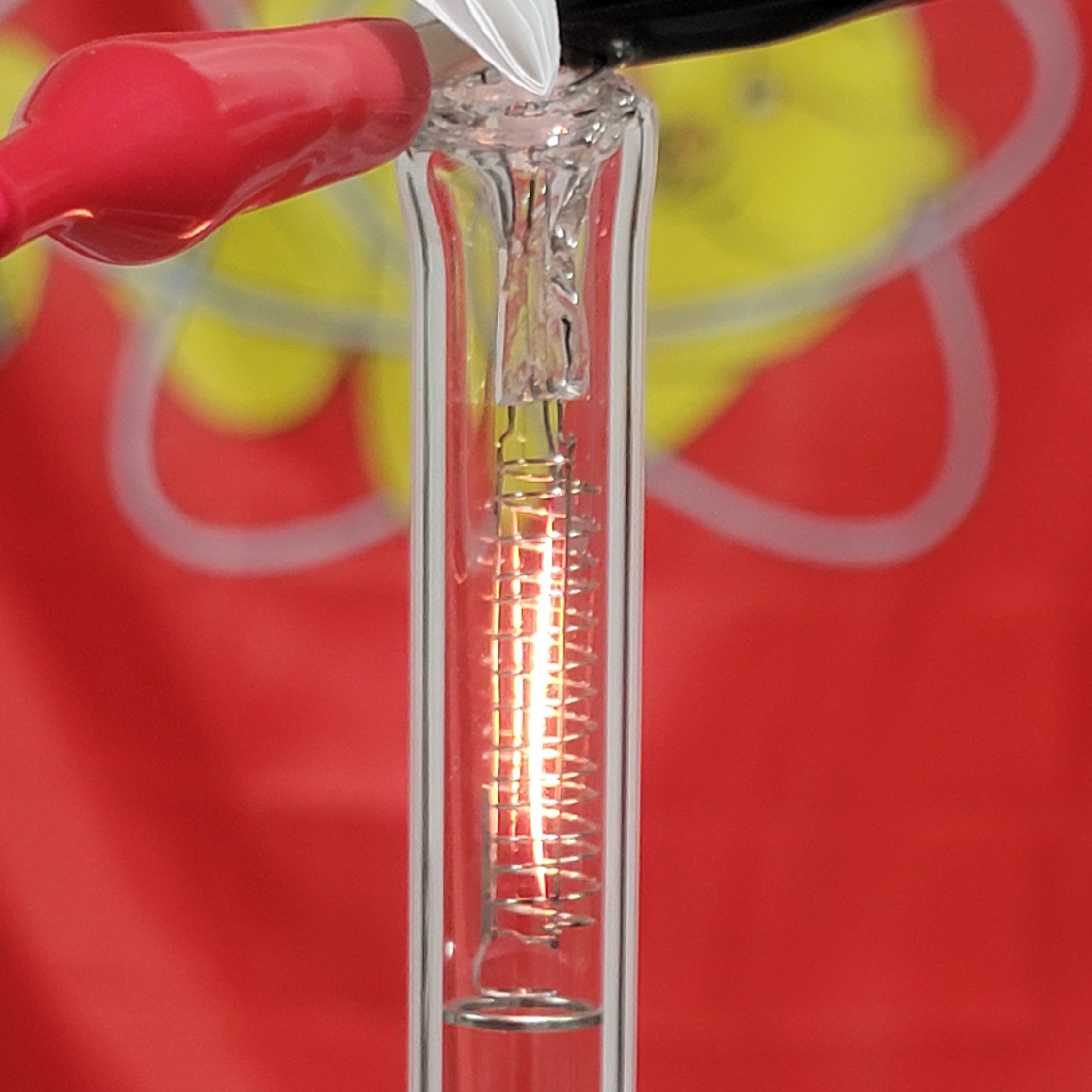
With the tube complete, I archived my photos and sent them off to Make: Magazine. In the meantime, I put the finished tube on my bench for testing. Sure enough, it’s a diode.

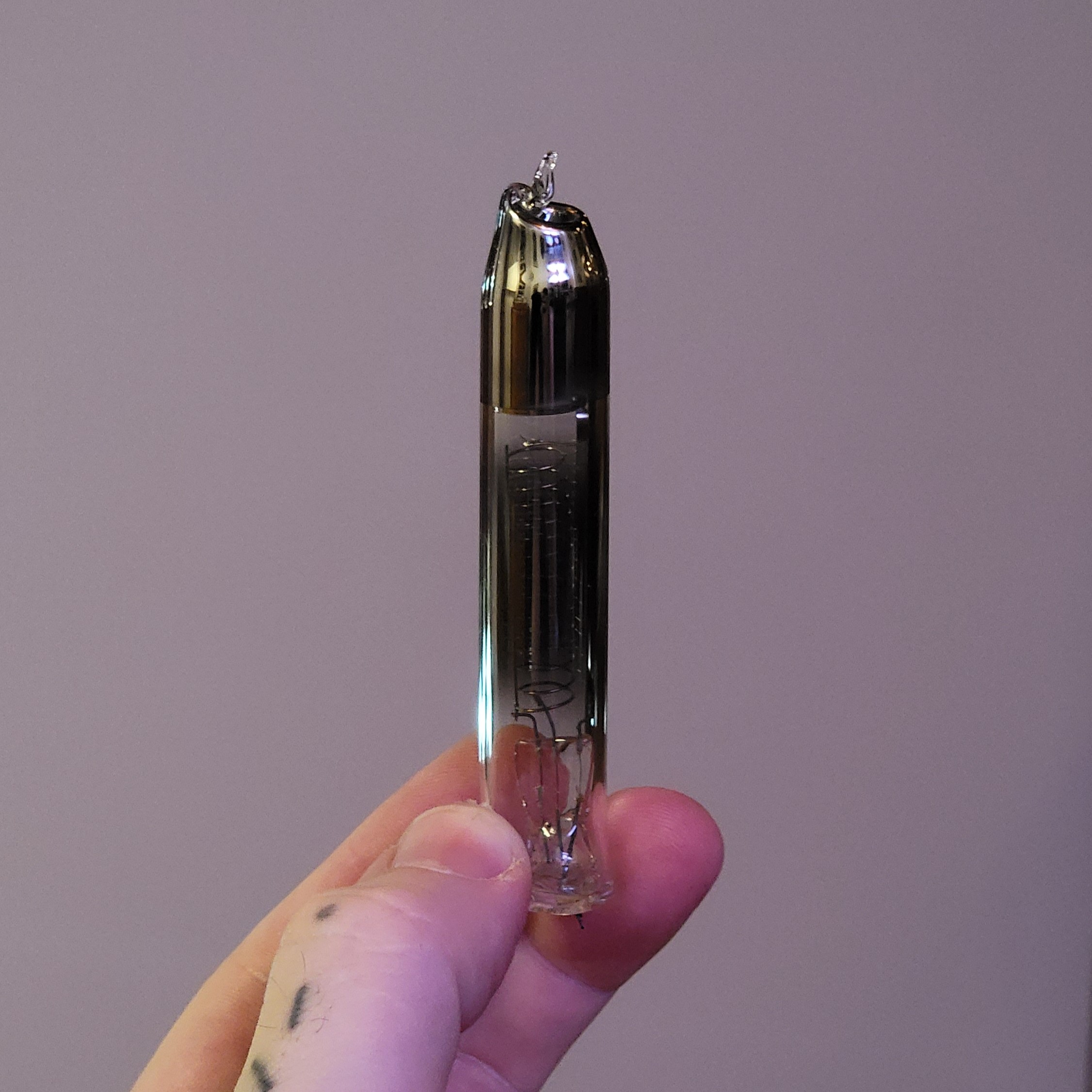
Of course, in the process of taking these photos, I got a little carried away with the filament current and tested it to destruction. That’s fine, I got the photos I needed. Besides, look at the beautiful Tungsten mirror it made:
I’m looking forward to building a curve tracer so that I can properly characterize these devices, but for now I’m just happy that several months later this tube still hasn’t leaked up.