Building an Oxikit O2 Concentrator (Part 1)
Scroll DownRunning out of O2
Earlier this year, I was working on an experimental tube when I ran out of oxygen for my torch. Usually this is just kind of annoying, since I work with borosilicate glass there’s no harm in losing my hot flame, I just give it a light annealing pass with my MAPP gas torch and come back to it later. This time, however, I was in the middle of the pinch. The pinch is where the base of the tube is heated until it’s extremely soft and the pass-through wires are pinched into it, forming a vacuum-tight seal. I was heating up to make the final pinch when my flame started to die and this essentially ruined the tube base. I was so angry that I vowed never to run out of oxygen again, and there was only one way to do this: pull it out of the fucking air.
This isn’t anything new, glass shops all over the world run oxygen concentrators to feed their torches. And why not? Hauling around compressed, or liquefied, oxygen is a pain in the ass. There are even companies that refurbish worn out medical oxygen concentrators for this purpose. Originally, this was my plan, to buy a worn out medical unit and fix it up. It turns out that this is harder to do than people say. Not for technical reasons, but for logistical reasons. Most medical supply resellers don’t list their busted equipment, and you can’t buy the not-busted equipment because it’s still medical equipment and you — presumably — don’t have a prescription. So you end up cold-calling a bunch of places to ask what they’ve got and then convince them to price it for you. Otherwise, you can wait for one to show up on a local marketplace board or auction site, but an alarming number of these are either scams or in awful condition. At the end of this process, if you’re lucky, you pay under $500 for an oxygen concentrator that will make 5L/min of >90% O2 for a hundred hours or so before you need to open the canisters and change out the zeolite anyway (we’ll talk about zeolite in a minute).
You could go the non-medical route, of course, there are companies that build “oxygen plants” for industry, but these are usually quite large, high-output installations that cost $$$ in exchange for high-reliability and industrial compliance.
So what can you do if neither of those sound appetizing? You can build one from scratch. Maybe a decade ago this would have been harder to do, but now it’s shockingly approachable. In fact, there’s even an open source hardware project!
Oxikit Project
India is battling with the worst 2nd wave of Covid-19 Pandemic. Several big hospitals across India are relying on daily oxygen supplies but they are not getting enough to keep some as backup in case of emergency.
While poking around the internet trying to learn the working principle behind commercial oxygen concentrators — and watching a lot of really excellent lectures from Indian universities on YouTube — I stumbled across the website of Oxikit, LLC. They’ve designed an open source oxygen concentrator that can be built from off-the-shelf parts to help address the shortage of medical oxygen in rural India resulting from the 2nd wave of COVID infections. They claim this machine can be built for under 3,000 USD and supply 15-20L/min of 94-96% pure oxygen. It’s hard to imagine how many lives have been saved by this project.
The documentation for the project is surprisingly complete and well-curated for an open source hardware project that was spun up so quickly. There’s a complete bill-of-materials, several system diagrams, and even a set of instructional YouTube videos showing how to construct the Oxikit concentrator step-by-step.
I immediately knew that this was the answer to my torch problem. At first, $3K sounds pretty steep, but looking at the BOM, there are a lot of corners I can cut because no one will be breathing this oxygen, so materials sourcing and component reliability aren’t as paramount. Also, I already had a lot of the components that I needed. Before we talk about my implementation of the Oxikit design, let’s talk about the working principle: Differential Adsorption.
Pressure Swing Adsorption Oxygen Concentrators
An oxygen concentrator has a lot of hoses and valves and stuff that all look very impressive, but the actual star of the show is a sand-like substance in the canisters that everything else is just there to support. This substance is zeolite: a microporous, crystalline aluminosilicate. In fact, it’s a very specifically structured form of zeolite called molecular sieves. If you’re familiar with the world of chemistry, you’ll have heard of these. Molecular sieves are made from different materials with different pore sizes and are used in a wide range of applications. In fact, if you know chemistry, the theory behind PSA oxygen concentration is going to sound a lot like column chromatography.
For all of the non-chemists, molecular sieves are little balls of ceramic material with a very carefully controlled pore size on the order of interatomic distances, usually measured in ångströms. One common molecular sieve is the 5A sieve, which has pores that are just the right size to adsorb water molecules and remove them from solution. These are used to dehydrate and store hygroscopic reagents by literally trapping water molecules that bump into them. The molecular sieves used in PSA oxygen concentrators are usually much smaller, having a larger surface area per mass, and usually have a 10A pore size — with 5A sieves are used in some applications. These sieves, “0.4-0.8mm 13X” sieves, have the consistency of fine playground sand — although they feel much more “slippery” because of their uniform semi-spherical shape. These zeolite sieves will selectively adsorb nitrogen molecules at a higher rate than oxygen. This means that atmospheric air entering one end of the sieve bed will leave the other end oxygen-enriched. Pretty quickly, of course, the sieve bed will become saturated, so what do you do then?
The PSA Cycle
The trick is to operate two sieve beds at the same time and “swing” the pressure back and forth between them. Take a look at the diagram below:
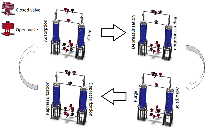
The adsorption capacity of the sieves will increase at higher pressures and we can exploit this property to grab nitrogen when we want to and then flush it out for the next cycle. Let’s focus on what’s happening in just one sieve bed:
Phase One: Pressurization
During the first phase, air is pumped into the sieve bed. In our case this pressure will reach about 30psi.
Phase Two: Adsorption
Under pressure, the nitrogen in the air will be selectively adsorbed onto the sieves, leaving oxygen free to move between them.
Phase Three: Depressurization
Now, the gas in the sieve bed is allowed to escape the opposite end. This gas is mostly oxygen, as it’s leaving the end with the highest concentration of oxygen and adsorbed nitrogen is slow to leave the sieves as the canister depressurizes. But this leaves a lot of nitrogen still in the canister, simply repressurizing at this point would result in a lower yield. We need to do one crucial step first.
Phase Four: Purge
During the purge phase, oxygen enriched air is flowed through the canister in the opposite direction. This flushes the nitrogen out and leaves the sieves ready to adsorb more nitrogen. The question you might be asking now is, where do we get this oxygen enriched air? The answer: Our other sieve bed.
Do the Swing
The reason this technique is called pressure swing adsorption is because the two sieve beds are operated out of phase with one another such that while one is pressurizing, the other is depressurizing. This means that while one is adsorbing, the other can be purging, and we can divert some of the output oxygen from one sieve bed to flush the other. This process can be repeated with a period of a few seconds to produce a steady stream of highly oxygen-enriched air.
Getting Your Hands on Sieves
You would think that such a magical material would be hard to come by, right? Or at the very least, extremely expensive. Luckily, they’re used in a LOT of industries for gas purification, desiccation, and exhaust scrubbing, so they’re made in massive amounts. This means that the cost for 0.4-0.8mm 13X zeolite sieves on AliExpress is about $50/kilo. About 3 kilograms of sieves are required for an Oxikit sized concentrator, so we’re talking about $150 worth of material. This zeolite will eventually wear out — although we do some clever things to slow this down as much as possible — but even with wear, these sieves will operate for hundreds of hours before losing enough efficacy to need replacing.
The Build
My oxygen plant would follow the Oxikit plan pretty closely, so the first order of business was to acquire the PVC plumbing parts and the zeolite. My zeolite arrived in 0.5 kilo vacuum sealed foil bags within just a few weeks of ordering from China. The PVC could mostly be sourced from a local hardware store, but because it’s all 3” Schedule 40, some of the fittings are a little hard to find. I ended up ordering all of mine online. It’s important that you use Schedule 40 pipe and not DWV, because the latter is not pressure rated and could crack or explode under pressure. Pressurizing gas inside of Schedule 40 PVC is already wildly out of spec, but at pressures of 30 psi and below, the risk is somewhat minimal.
Sieve Canisters

Here you can see all my end-caps staged for assembly. Every part needs to be cleaned, primed, and glued together using PVC cement. Here you can see two caps for each sieve bed and then a third set of caps for an empty canister that will be used as a buffer tank to remove the pressure oscillations from the output stream. You might think it’s as easy as just filling some 3” PVC with sieves and slapping these on the ends — and it almost is — but there are few things we need to do first.
Because the canisters are constantly being pressurized and depressurized, and being subjected to flow in both directions, the sieves will have a tendency to shift back and forth in the canister. This shifting will pulverize the sieves over time, rendering them ineffective and contaminating the output stream with fine zeolite dust. To avoid this, we need to “pre-load” the sieves so that they’re under constant mechanical pressure and thus can’t shift during the pressure swing. This is achieved using a piston and a spring. The Oxikit uses a pair of fairly exotic stainless steel, flat, peak-to-peak wave springs for this. That makes sense for their application, the stainless steel will have a long service life without reacting in the oxygen-rich environment and the wave springs can achieve a high spring ratio in a low profile. I opted for a cheaper and more accessible option. I found these transfer assist springs for racing suspension.
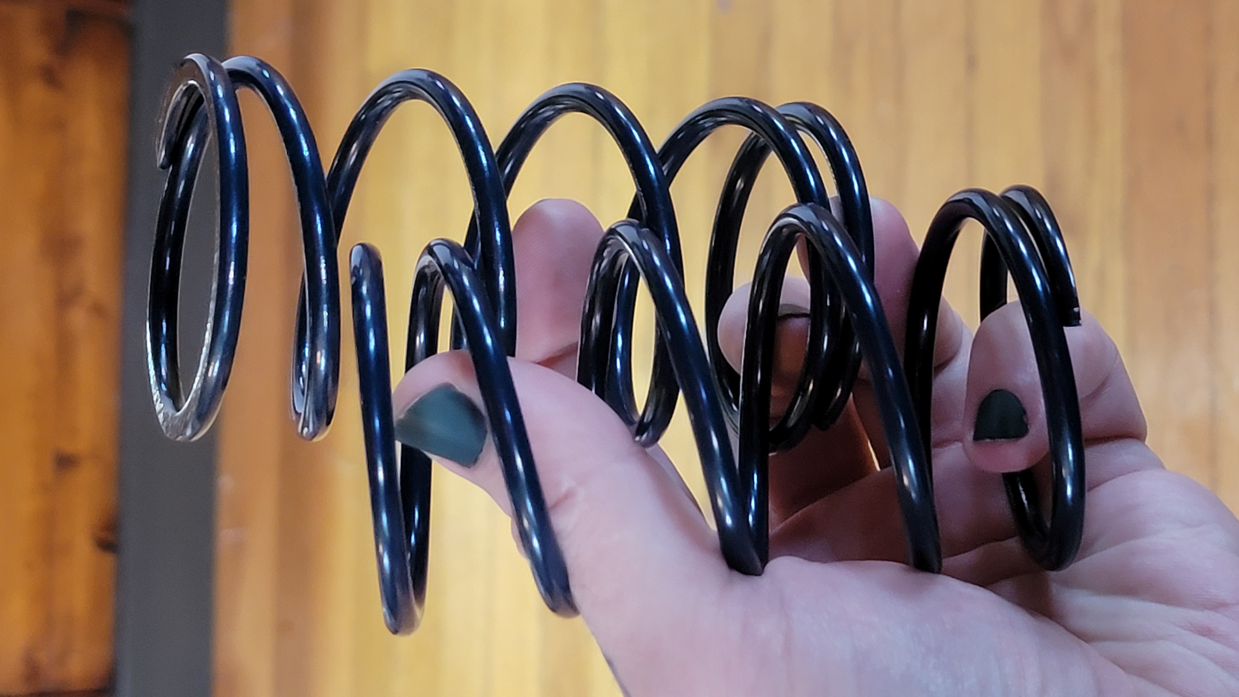
They have the same spring rate as the springs that are spec’d from Oxikit, but they’re normal coil springs. They’re not going to be as resistant as the stainless steel, but at least they’re powder coated. Oxygen will transport through the epoxy layer and slowly rust the spring, but I expect they’ll have an adequate service life and because this is a non-medical application, there’s nothing wrong with a little contamination in the output stream.
Another difference in my design is the piston construction. The Oxikit project has a very clever piston assembly made out of modified PVC fittings. I think this is a great solution for a machine to be built with no custom-manufactured components. In my case, however, I’m in no rush and I have a 3D printer, so I designed a piston and a spring seat to print on my trusty Creality CR10.
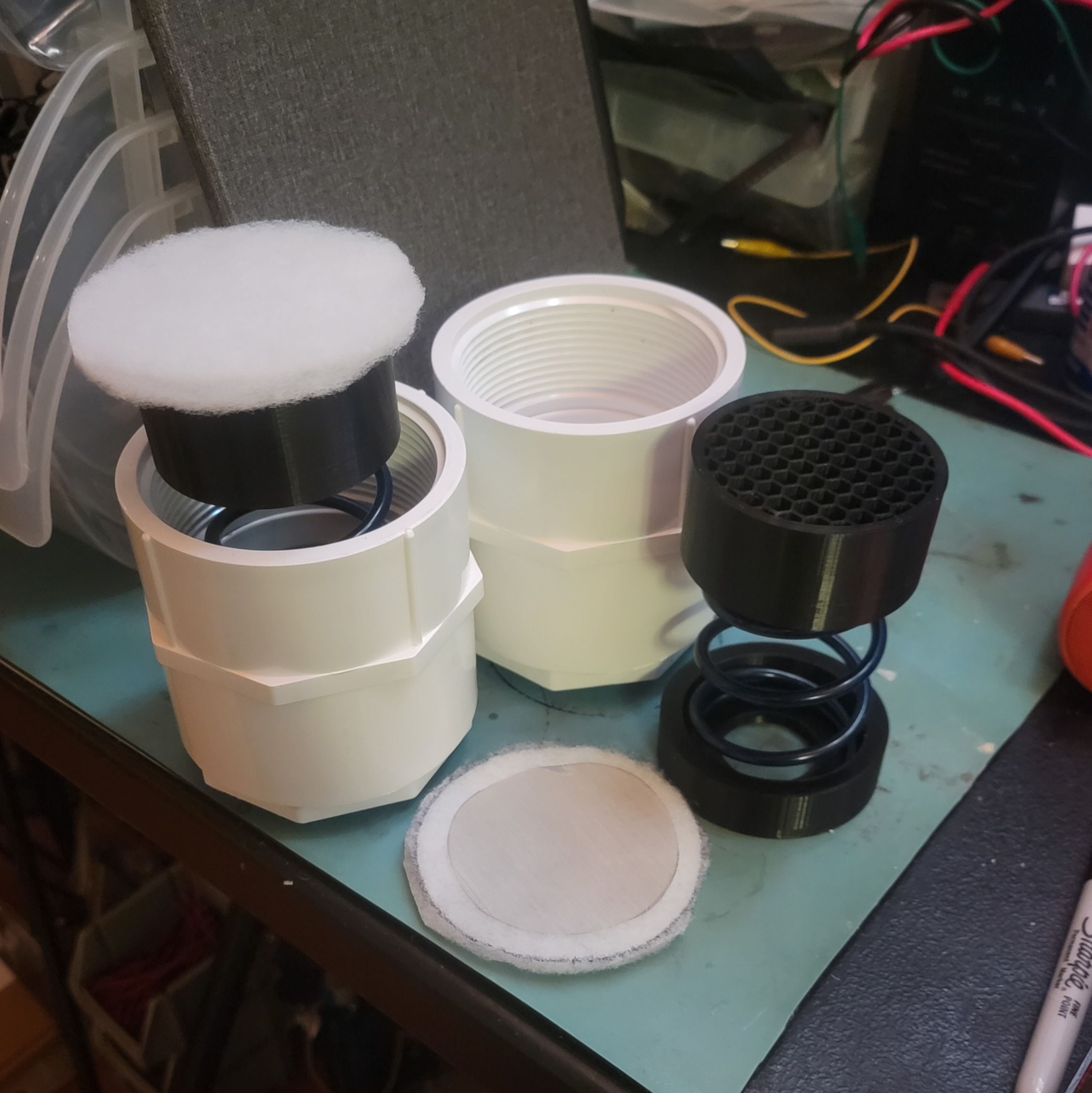
The spring seat sits flat against the PVC bushing and keeps the spring centered in the assembly. The piston is permeable, so that the process gas can run through it, but makes a tight fit with the inside of the canister. The face of the piston is covered with fine stainless steel mesh and two layers of non-woven filter material. The filter material is allowed to drape the sides of the piston to act as a piston ring and form a seal between the piston and the cylinder wall, preventing zeolite from being blown past the piston. A similar arrangement of screens can be found at the other end as well, I also modeled and printed the screen support for this instead of modifying an off-the-shelf fitting. The piston assembly is built around a pair of threaded PVC fittings so that the sieves can be packed into the canister and then the piston assembly can be screwed down onto the end, compressing the spring and applying the pre-load.
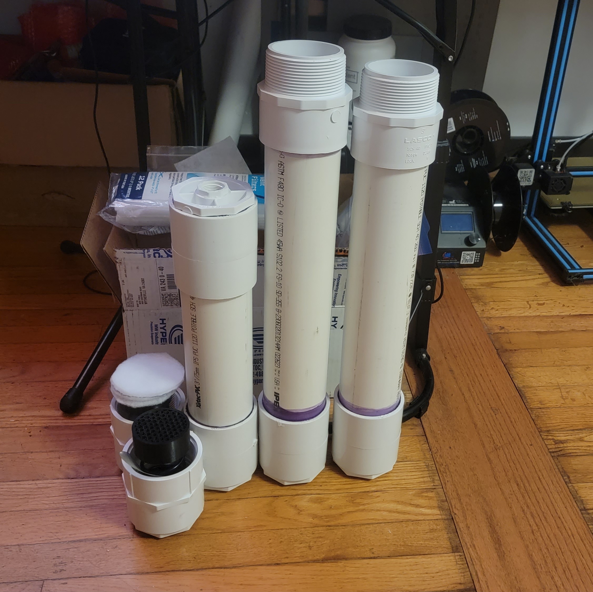
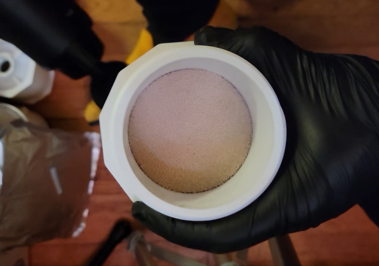
In the photo above, one of the sieve beds is considerably shorter than the other because I wasn’t able to make some of the fittings seat all the way. This bothered me so much that I ended up buying more parts and rebuilding that sieve canister. The next step is to fill them with zeolite. The Oxikit videos recommend using an air hammer at a very low setting to agitate the sieves as you fill the canister, this ensures that they’re tightly packed and won’t settle during operation, taking up the slack in the pre-load spring and getting pulverized over time. I opted to use a Theragun-style vibrating massage gun, which was plenty powerful enough to make the sieves dance in the canister. During this operation it’s important to wear a good dust mask because it will generate a fair amount of mineral dust that’s very bad for your lungs. I had a half-face respirator with P100 pre-filters handy, so I just wore that.
After filling the sieve canisters and making sure that they were well-packed, all that was left was to screw down the piston assemblies. This was achieved with two strap-wrenches and a lot of elbow grease. Before the assembly went on, however, the threads got a liberal coating of thread compound to seal it against gas leaks. Thread compound was used on all PVC threaded connections as opposed to Teflon tape because the tape tends to split parts if you over-torque it or apply too much. And with that, that’s our sieve beds and buffer tank finished!
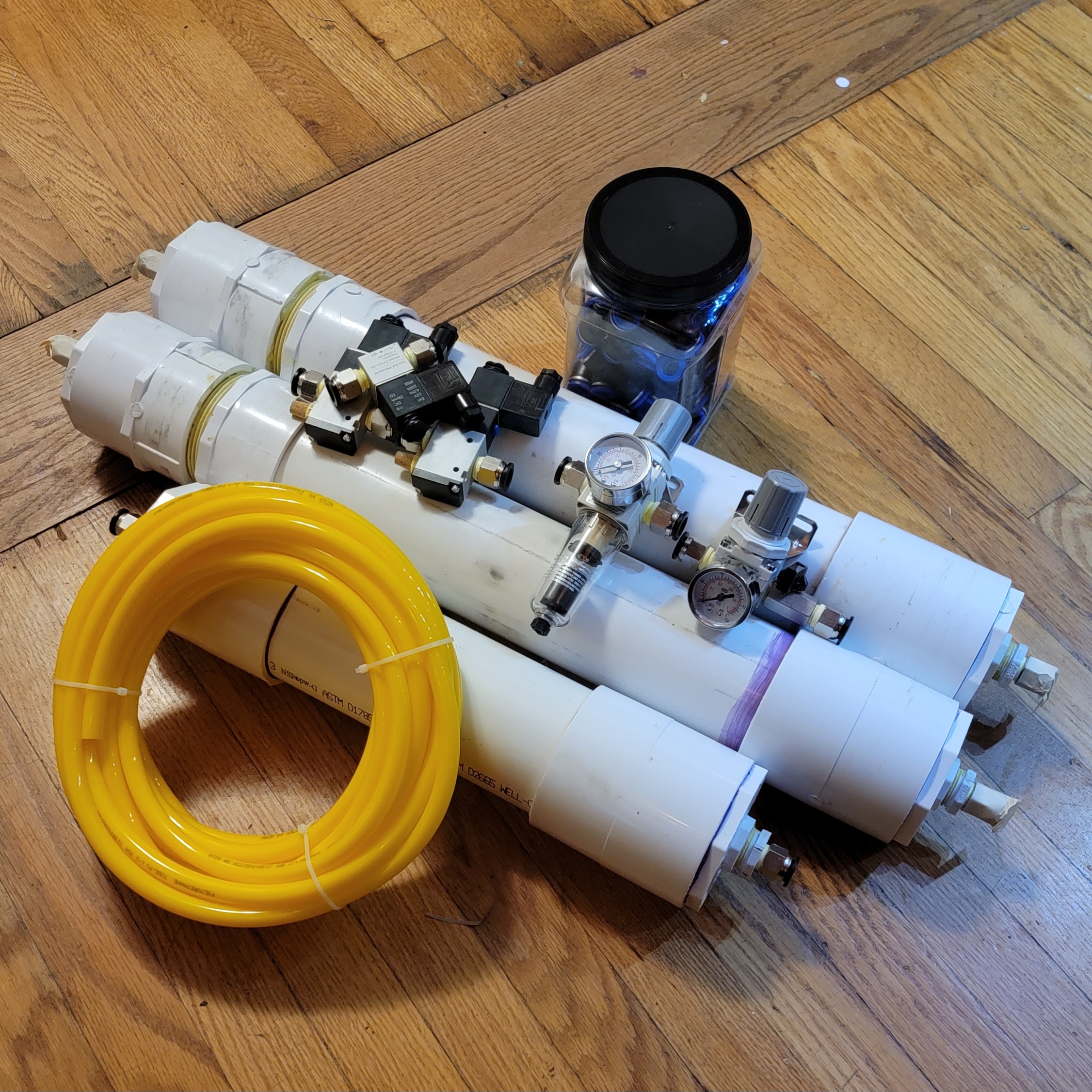
Meanwhile, I had been gathering the pneumatic valves and fittings to plumb everything together. But before we talk about valves, we need to talk about our compressed air source.
Cool, Dry, Oil-Free, Compressed Air
The air compressor will the be most expensive single component of the build, even counting the zeolite in the sieve beds. You may think that you could run your shop compressor into it, and if you have an extremely fancy shop then maybe you could, but my shop compressor is not particularly fancy and the air that comes out of it is well-contaminated with water and oil. This is a problem for multiple reasons. Water will clog and destroy the molecular sieves, as will oil. But oil has an even more disastrous effect on the system, because after the sieves it will be in contact with compressed oxygen and this could potentially cause it to rapidly oxidize, resulting in fire or explosion.
The compressor pump that Oxikit specs for this task is a 2HP, 2-cylinder, electric diaphragm pump. Diaphragm pumps are great because they contain no oil and so they introduce no oil to the air stream. The downside is that they’re more expensive than oil-sealed piston pumps for the same flow rate. Oxikit has offered this pump in their shop for $600, which is about the going rate, but it hasn’t been in stock for some time and I’d hate to divert a pump from medical use. I found that a nearly identical pump was being sold by California Air Tools as a replacement motor for their compressors at about half that price. This compressor pump is available from a number of distributors including Global Industrial, Grainger, Northern Tool, and Tractor Supply. I ended up ordering mine from Tractor Supply and it arrived in about a week.
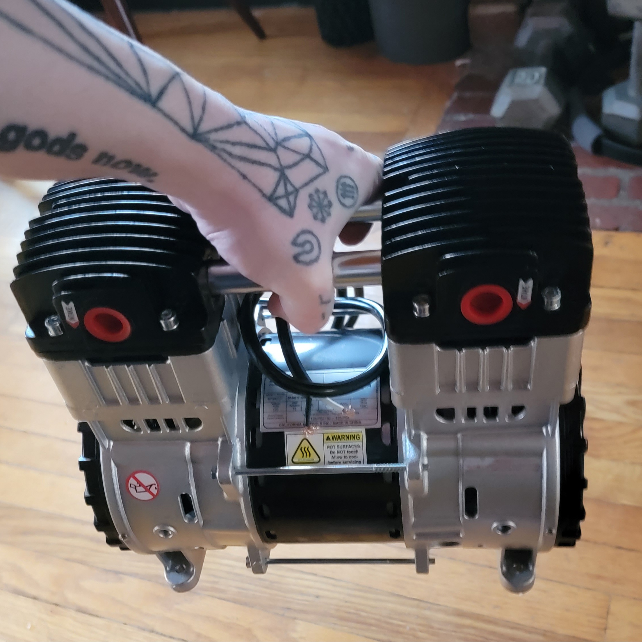
The pump comes with a pair of mufflers, an elbow for the output, and the running capacitor. Oddly, it doesn’t come with a plug for the unused output port, but those are easy enough to find. Although the specs say that the pump has 3/8” NPT ports, this is not true. The ports in the cylinders themselves are actually 1/2” NPT and the included elbow is a 1/2”-3/8” reducer. You’ll need a 1/2” NPT plug. This little thing is DENSE, it’s a 2HP electric motor. It also comes with a set of rubber isolators that thread into the feet. I ended up buying a separate set because I needed a lower profile stud, but it’s nice that they’re included because they probably wear at a similar rate to the pump. This is intended to be a replacement kit, after all.
Now we have oil-free air, but it’s going to be quite warm coming out of the compressor and if you live in the southeastern US like me, it’s gonna be WET. To solve these problems, we’ll employ a large copper coil to cool the air. Cooling the air will also lower its capacity to hold moisture, so we’ll condense a lot of the water out of it as well. I made my condenser out of 3/8” soft copper tubing. I suppose it would be possible to use a pre-build condenser for this application. Something like an automotive heater core would probably work fine, and you might even get away with a PC water cooling radiator, but 30psi might be asking a lot of some of the cheaper offerings. If you don’t mind the tedium of bending copper tubing, it’s the cheapest and most effective solution, and it’s the solution recommended by Oxikit. My coil will sit overtop of my compressor, so I started it with a vertical leg that I covered in foam insulation to prevent condensed water from running back into the compressor. The other end of the coil connects to a pressure safety valve to keep the system below 40psi as well as a water trap so that condensate running out of the coil can be captured and drained.
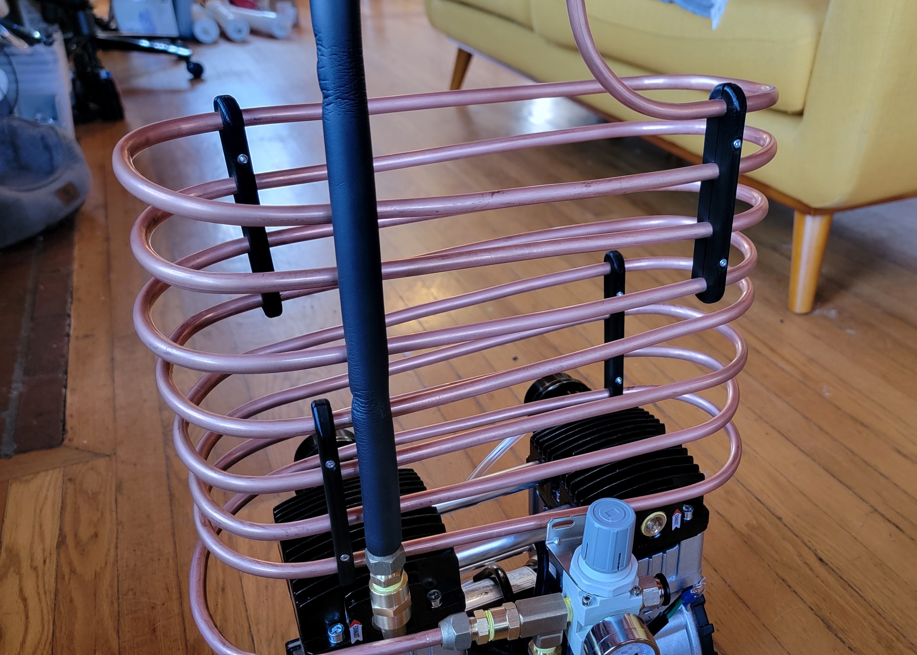
I designed and 3D printed a bunch of brackets to hold the coil in position, keep the coil spacing even, and prevent it from vibrating too much. Eventually, the coil would be rigidly mounted to a frame that’s isolated from the pump with rubber isolators.
Pneumatic Control
The final challenge is to control the flow of compressed air between all of the parts of the system. To achieve this, I opted for cheap TAILONZ solenoid valves on Amazon. These will inevitably fail, but at $16/pc, they’re replaceable. The system is plumbed with 1/2” OD PU air tubing and quick-connect fittings.

There are two pressure regulators on the system. One is after the compressor to ensure that the system is only exposed to about 30psi. The other is the output regulator which gets set to just a few psi. Make sure that anything with a gauge on it after the sieve beds is equipped with an oil-free gauge. Two oil-free gauges designed for oxygen service were installed on the sieve beds as well to monitor the pressure swing during operation. All of these parts were sourced extremely cheaply from Amazon.
Mechanically Complete System
The Oxikit system is built on a wooden frame, which is a cheap and sturdy solution but not very convenient for my application so I chose to build mine on wheels. Originally, I started to design a custom chassis using aluminum t-slot extrusion, but I quickly noticed that I was essentially designing a hand-truck, so instead I commandeered a hand-truck from my shop and used that. I modeled and printed custom mounting brackets for everything and attached them with M5 hardware. The compressor was bolted to the platform using rubber vibration isolating standoffs.
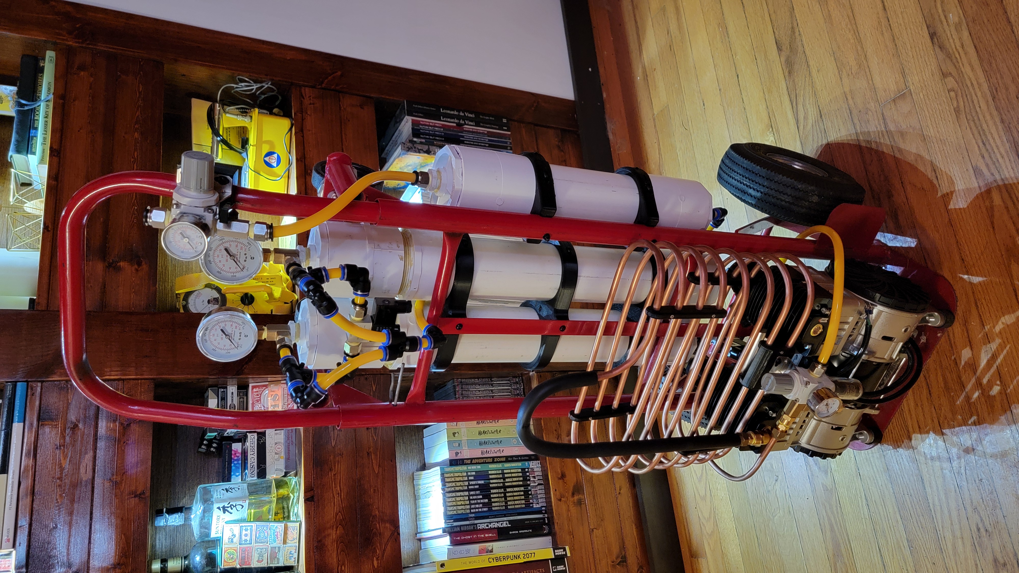
That’s the whole thing, completely assembled except for the electronics. I have yet to finish the electronics portion, but I plan to attach DIN rail to the front of the chassis and use that to mount the electronics. Keep an eye out for part 2, where I’ll elaborate on the electronics and we’ll test the system!